- File : Application Note AN-EK016-EN - PDF - 5 350 ko - 65 pages (on going redaction).
- Version : 1c
- Date : August 9, 2025
- Sébastien JACQUES
- Thierry LEQUEU -
Cette adresse e-mail est protégée contre les robots spammeurs. Vous devez activer le JavaScript pour la visualiser. - See also: AN-EK016-FR - Utilisation de DVTC pour les variateurs SEVCON GEN4
- See also: DVTC - La dernière version du logiciel DVT pour variateur SEVCON GEN4
- See also: SEVCON DVTC configuration software for SEVCON GEN4 controllers
Bibliography :
[1] : Thierry LEQUEU, « AN-EK015-FR - Installation du logiciel DVT pour les variateurs SEVCON GEN4 », 12 pages, janvier 2013.
[2] : Paul Shipley, « Application Note - DVT Installation (draft) », December 2nd, 2009, 6 pages.
[3] : Web site of the company BORGWARNER (SEVCON), www.borgwarner.com, accessed August 9, 2025.
[4] : SEVCON, « Gen4 Product Manual », version 3.4, de décembre 2015, 115 pages, 3256 ko.
[4] : BorgWarner, « Gen4 Product Manual », version 4.4, de janvier 2024, 131 pages, 3706 ko.
[5] : Arnaud SIVERT, « AN-EK005-FR - Didacticiel pour variateur GEN4 SEVCON (moteur AC) V2 », 32 pages, avril 2010.
[6] : Web site of the company HMS Network for the XXAT, www.hms-networks.com - IXXAT USB-to-CAN, accessed August 8, 2025.
[7] : Société SEVCON, « SEVCON DVT Tutorial - Using DVT with Gen4 Systems », 11 pages
[8] : Web site of the company ActiveState, www.activestate.com - tcl, accessed August 9, 2025.
[9] : H. SLATER, P. SHIPLEY, « SEVCON - Setting up PMAC software », révision 14, du 18 mai 2018, 28 pages, 652 Ko.
[10] : Thierry LEQUEU, « Exemple de câblage du circuit électrique d'un véhicule », accessed August 9, 2025.
[11] : Dave CONBOY, « App Note - KTY83-84 Obsolescence », May 22, 2015, 4 pages.
See also:
- BorgWarner GEN4 Product Manual V4.4 - 2024
- How to set the Battery Current Limit on a SEVCON GEN4 controllers
- BorgWarner GEN4 Product Manual V4.2 - 2022
- SEVCON GEN4 Product Manual V3.4
- SEVCON Application Note PMAC, 28 pages, 652 Ko.
- L'erreur 0x4682 IO Init sur un variateur SEVCON GEN4
- Documentations SEVCON GEN4 version 3.2
- Pilotage d'un variateur SEVCON GEN4 par un automate
- Les utilisateurs des variateurs SEVCON
- Les variateurs GEN4 de SEVCON
- Exemple de câblage du circuit électrique d'un kart.
- L'interface USB-CAN compact IXXAT V2.
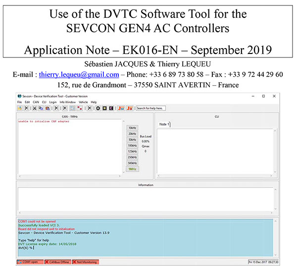
Table of Contents:
1 Introduction 5
1.1 Foreword 5
1.2 Pre-launch Verification of the DVTC Software Tool 5
1.3 Launching theDVTC Software Tool 5
1.4 Choice of theTransmission Frequency of theCAN bus 6
1.5 The "Information" Window 7
1.6 The Online Command Window 7
1.7 The Other DVTC Software Modules 8
2 The"Helper" Script–Getting Started with the SEVCON GEN4 AC Controller 9
2.1 Foreword 9
2.2 Creating the EDS File when the "Helper" Is Launched 9
2.3 The GEN4 Controller Home Screen 9
2.4 The "Input/Output" Tab – Definition of Inputs/Outputs 11
2.5 The "Tree" Tab – Function Settings 13
2.5.1 The « Search » Button 13
2.5.2 Setting of the Line Contactor 13
2.5.3 A Few Words about Voltage Reduction 15
2.5.4 Accelerator Pedal Settings 16
2.5.5 Automatic throttle pedal setup 17
2.5.6 Parameter Setting of the Motor Temperature Sensor 18
2.5.7 Configuring the PT1000 temperature sensor 19
2.5.8 Voltage Limits of the Battery 20
2.5.8.1 The Limits of the "app_cutback" Battery 20
2.5.8.2 Limiting Voltages of the "motor_cutback" Application 21
2.5.8.3 Limiting Voltages of the SEVCON GEN4 AC Controller 22
2.5.9 The various torque limitations 23
2.5.10 Motor Torque-Speed Characteristic 24
2.5.10.1 Setting the Motor Limits: the "Profiles" 24
2.5.10.2 "Traction Baseline Profile" 25
2.5.10.3 "Driveability Select 1 Profile" 26
2.5.10.4 "Driveability Select 2 Profile" 27
2.5.10.5 “Driveability Select 3 Profile” 27
2.5.11 Setting cooling parameters based on temperature. 28
2.6 Managing DCF Configuration Files 29
2.6.1 The "Save DCF from unit" menu 29
2.6.2 File Naming 29
2.6.3 The "Send DCF to Unit" Menu 30
3 The"Helper" Script – Advanced Functions 32
3.1 Changing the Access Level 32
3.2 Changing the Nominal Voltage and Current Values 32
3.3 Loading a "Software DLD" File into the Controller 34
3.3.1 Saving the Controller Configuration 34
3.3.2 The “Reprogram Unit Firmware” menu 34
3.3.3 Switching to the "Bootloader" mode 35
3.3.4 Programming a New "Software" 35
3.3.5 Exiting the "Bootloader" Mode 35
3.3.6 In Case of Problems 36
3.3.7 After Updating a New "Software" 36
3.4 The "TPDO/RPDO" Tab 37
3.4.1 Some References on this Topic 37
3.4.2 Configuration of "RPDOs" 37
3.4.3 Configuration of "TPDOs" 38
3.5 The "Change Baud Rate" Menu 40
3.6 Definition of the Motor Characteristics 42
4 The "Vehicle Interface" Script 43
4.1 Introduction 43
4.2 Data Display 43
4.2.1 The Output File 44
4.2.2 The Control Buttons 44
4.3 Data Processing Using EXCEL 44
5 The "Editor" Script 47
5.1 Introduction 47
6 References 48
7 Appendix1 – Checks Before the Launch of DVTC 49
7.1 The Controller Wiring – Power Part 49
7.2 The Controller Wiring – Control Part 49
7.3 Checking the USB-to-CAN interface 50
8 Appendix2 – Numbering of SEVCON GEN4 AC Controllers 52
8.1 Product identification label 52
8.2 Numbering of SEVCON GEN4 AC Controllers 53
8.3 Glossary of Terms 53
9 Appendix3 – Online IT Orders 54
9.1 The Principle of Tcl/Tk Commands 54
9.1.1 Displaying a Text 54
9.1.2 Comments 54
9.1.3 Variables 54
9.1.4 Calculations 54
9.1.5 Calculation loops 54
9.1.6 Declaration of Procedures 54
9.2 CANopen Commands of SEVCON GEN4 AC Controllers 55
9.2.1 Manual Loading of a DCF Configuration File 55
9.2.2 List of "Active Faults" 55
9.2.3 Manual Loading of a DLD "Software" File 55
10 Appendix4 – The Variables of the Motor 57
10.1 The "Save Partial DCF" Command in the "DVTC Helper" 57
10.2 List of Variables Provided by "Add PMAC Motor Items" 58
10.2.1 Variable 0x4611 – Motor power limit map 59
10.2.2 Variable 0x4615 – Motor power limit map 2 59
10.2.3 Variable 0x4617 – Programmable User Data 59
10.2.4 Variable 0x4620 – Motor Temperature 1 (Measured - T1) 59
10.2.5 Variable 0x4621 – Motor Temperature Setup 59
10.2.6 Variable 0x4620 – Encoder Configuration 59
10.2.7 Variable 0x4640 – Motor Nameplate Data 60
10.2.8 Variable 0x4041 – AC Motor data (manufacturer specific) 60
10.2.9 0x4650 Variable – Miscellaneous DSP Configuration (Gen4) 61
10.2.10 0x6072, 0x6075 and 0x6076 Variables 61
10.2.11 0x6090 Variable – Encoder Resolution 61
11 Appendix5 – Tips for Adjusting Correctors 62
11.1 Speed Loop 62
11.2 Current Loop 62